E. Tuncer, Beom-Taek Lee, and D. P. Neikirk, "Interconnect Series Impedance Determination Using a Surface Ribbon Method" IEEE 3rd Topical Meeting on Electrical Performance of Electronic Packaging, Monterey, CA, Nov. 2-4, 1994, pp. 250-252.
Interconnect Series Impedance Determination Using a Surface Ribbon Method
Emre Tuncer, Beom-Taek Lee, and Dean P. Neikirk
Department of Electrical and Computer Engineering
University of Texas at Austin
Austin, Texas 78712
Tel:(512) 471-4669
Fax:(512) 471-5445
Abstract
In this paper we apply the current filament method to surface "ribbons" instead of volume filaments, leading to a substantial reduction in problem size and increase in computational efficiency. The accuracy is excellent when compared to "full Weeks'" calculations, with a factor of almost 100 reduction in CPU time.
Introduction
Determining the frequency dependent total series impedance for an interconnect on a Multi-Chip Module (MCM) can be an arduous task. Various methods have been proposed for this task, such as Weeks' filament method [1] and conformal mapping techniques [2]. Efficient application of the latter technique depends fundamentally upon a calculation of the surface impedance of the conductors that represents the "internal" behavior of the conductors; conformal mapping then solves the exterior problem. In this paper we show that surface impedance can also be used in conjunction with the filament method. Using surface impedance, one has to solve only the exterior problem, and so the filament method can be applied to surface "ribbons" instead of volume filaments. This leads to a substantial reduction in problem size, with a corresponding increase in computational efficiency. Here we show that there are several alternative approaches to find approximate values of surface impedance, and that the accuracy of this technique is excellent when compared to a "full Weeks'" volume filament calculation, with a factor of almost 100 reduction in CPU time.
Surface Impedance Models
Surface impedance can be defined as the ratio of total tangential electric
field to total tangential magnetic field at the conductor surface at a given
frequency. Surface impedance of an seminfinite conductor slab is , where u and [[sigma]] are permeability and conductivity
of the conductor, respectively. When the thickness of the slab is finite,
the surface impedance is just
, where
and d is the thickness of the slab [3]. For more useful conductor geometries
calculation becomes much more complex. The surface impedance can also be
calculated from a conventional filament method. After the current distribution
is found for particular frequency, the magnetic field is calculated at the
surface by integration. The electric field is obtained from the current
density for the filament at each surface location. The current density at
the actual surface is approximated by fitting an exponential curve to the
current distribution calculated from the filament method.
To approximate the surface impedance of a thick rectangular bar Jingguo et al. calculates surface impedance assuming four plane waves incident normal to the surfaces of the conductor (Technique A) [4]. Another method uses geometrical segmentation to mimic electromagnetic wave distribution inside the conductor with non-uniform transmission lines (Technique B) [5]. A modified version of this method is obtained by making the conductor a hollow tube, with wall thickness of 3d (where d is the skin-depth) as the frequency increases (Technique C). For the corner regions the same technique is used as in [5], while for the rectangular regions the simple hyperbolic tangent expression is used. However, since the thickness of the wall is always 3d, the argument to the special functions (hyperbolic tangents and the Bessel functions in [5]) is always the same at each frequency once the frequency is high enough such that 3d is smaller than thickness of the conductor. For lower frequencies the dc resistance is used for that section. As a final method, the surface impedance can be calculated by first segmenting the conductor into two triangles and two trapezoids, and then for each segment the hyperbolic tangent expression is used with d (thickness) a function of position on surface such that d equals to the depth of the segment at that location (Technique D).
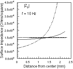
Figures 1a & 1b show the results of the full volume filament calculations for surface impedance, as well as the results of Techniques A-D. A square copper bar with side length t = 4.62 mm was used to test the models, to match the dimensions of the bar used in the experimental work of [6]. Techniques A-C all predict a position independent surface impedance at low frequency (d >> t), although the exact result for uniform current distribution is not constant, as shown by the volume filament calculation. Technique D does produce a higher impedance near the corners, but is low at the center of the bar. All models (when integrated over the surface) produce the correct dc resistance. As the frequency increases and d << t, the volume filament calculation and techniques A, C, and D tend to 1/[[sigma]]d near the center of the bar. All techniques give reasonably good agreement for the total series impedance of an isolated square bar, as measured by [6].
Modified Filament Method for Coupled Lines
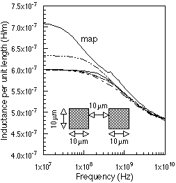
The volume filament method divides the conductor into rectangular filaments that fill the entire cross section of the conductor. The size of the problem can be reduced by considering only the surface of the conductor. Instead of using "volume filaments" we use "surface ribbons," each assigned an impedance based on the surface impedance appropriate for that location on the conductor surface. The reduction in the size is thus from N**2 to 4N, where N represents the number of segments per side used. As a test case, we have calculated the series impedance of a two conductor transmission line using Weeks' filament method and by the modified filament method for surface impedance approaches discussed above. The copper conductors are coplanar, 10um thick and 10um wide, separated by 10um. For the volume filament method each conductor is divided into a 20x20 mesh, resulting in 800x800 matrix size. For the surface ribbon method the same mesh is used, but this time only at the surface. The size of the matrix for the latter case is 160x160. Figure 2 compares the series impedance per unit length for the coplanar bars found with the different models. For comparison, the conformal mapping result from [2] is also shown. All techniques are in good agreement for the series resistance of the interconnect. The main discrepancies are in the low frequency inductance; the conformal mapping is highest, followed by the surface ribbon calculation using surface impedance technique D. Volume filament and surface ribbon calculations are in excellent agreement over the full frequency range for techniques A, B, and C.
The main advantage of the surface filament approach is seen when CPU times are compared. For the ten frequency point calculation shown in Fig. 4, the volume filament calculation required 3 hrs on a Sparc 10 workstation.; the same curve required only 100 sec to calculate using the surface ribbons (including the calculation of the surface impedance). The conformal mapping calculation required only 48 sec (including both surface impedance and map coefficient calculations), although at the cost of loss of accuracy in inductance at low frequency. It should also be noted that most techniques designed to speed up volume filament calculations can also be applied to the surface ribbon approach. In conclusion, we have shown several surface impedance models, that when used in combination with a surface ribbon calculation, can efficiently and accurately find the series impedance per unit length of multi-wire lossy interconnects.
References
1. W. T. Weeks, L. L. Wu, M. F. McAllister, and A. Singh, "Resistive and inductive skin effect in rectangular conductors," IBM J. Res. Develop., vol. 23, pp. 652-660, 1979.
2. E. Tuncer, B.-T. Lee, M. S. Islam, and D. P. Neikirk, "Quasi-Static Conductor Loss Calculations in Transmission Lines using a New Conformal Mapping Technique," to be published in IEEE Trans. Microwave Theory Tech., Sept. 1994.
3. A. E. Kennelly, F. A. Laws, and P. H. Pierce, "Experimental researches on skin effect in conductors," Trans. AIEE, vol. 34, pp. 1953-2018, 1915.
4. W. Jingguo, J. D. Lavers, and Z. Peibai, "Modified surface impedance boundary condition applied to eddy current problems," IEEE Trans. Magnetics, vol. MAG-26, pp. 1197-1200, 1992.
5. E. Tuncer and D. P. Neikirk, "Efficient Calculation of Surface Impedance for Rectangular Conductors," Electron. Lett., vol. 29, pp. 2127-2128, 1993.
6. S. J. Haefner, "Alternating-current resistance of rectangular conductors," Proc. IRE, vol. 25, pp. 434-447, 1937.

(a) (b)
Figure 1: Magnitude of surface impedances from various methods as a function
of position from the center of the face of a 4.62 x 4.62 mm copper bar at
10Hz and 20KHz, respectively. Solid line: volume filament method (from Weeks,
[1]); Jingguo et al., Technique A [4]: ; Technique B [5]:
; Technique C:
; Technique D:

(a) (b)
Figure 2: Series impedance per unit length for copper, coplanar
bars, calculated from the volume filament and surface ribbon methods using
various surface impedance models. Solid line: volume filament method (from
Weeks, [1]); surface ribbon method, ZS from Jingguo et al., Technique A
[4]: ; ZS from Technique B [5]:
; ZS from Technique
C:
; ZS from Technique D: