Vikas I. Gupta, Dean P. Neikirk
The Dept. of Electrical and Computer Engineering
The University of Texas at Austin
Austin, TX 78712
Eddy-current sensors have been studied for a number of years as a method of non-destructive testing and non-contact measurement. Macroscopic proximity sensors based on the eddy-current techniques are commercially available. However these proximity sensors are not conducive to scaling to conventional integrated circuit levels. This is because most conventional eddy current proximity sensors use a single inductor. For miniature inductors fabricated using integrated circuit techniques, as the inductor is scaled down the inductance decreases while the resistance of the coil increases dramatically. This means that the sensor needs to be operated at much higher frequencies for which the inductance of the coil dominates its resistance, i.e., [[omega]]L >> R.
Laser interferometric sensors and capacitive sensors have also been used as microscopic proximity sensors. Laser interferometric sensors measure relative distances and need to be interfaced with optical fibers. Capacitive sensors need an electrical contact with the 'other' surface. These restrictions make their use difficult in many applications.
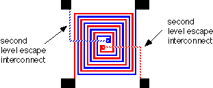
We have developed a new inductive proximity sensor design that makes use of two coupled coils, forming a planar transformer. Shown in Fig. 1 is the test set-up for a two-coil spiral transformer studied as the transducer for the proximity sensor. The two coil-transformer is shown in Figs. 3 and 4. More information on the fabrication issues involved in this micromachined sensor can be found here. Measured results for the characteristics of this structure are shown in Fig. 5. A significant sensitivity to gap is shown in the relative phase difference between the primary and secondary windings of the planar transformer.
We have developed an accurate PSpicereg. model for this sensor (Fig. 2), as well as a method for the calculation of the necessary component values for the circuit (resistance, self-inductance and mutual-inductance of the coils and the metal plate). The invariance of the phase plot with change in coil resistance (due to either temperature change or change due to scaling to IC levels) is a critical feature for the successful operation of a miniature IC inductive proximity sensor. Using our two coil approach, the sensor can be operated at lower frequencies than those required for a single coil eddy-current sensor. Potential applications using two-coil planar inductive devices include bearing wear sensors, small gap measurement, and accelerometers.
Fig. 1: Test set-up for proximity sensor consisting of two coupled coils (forming a transformer) used to measure the distance to an electrically-floating metal plate.

(b)
Fig. 2: Basic circuit model of two coupled-coil proximity sensor used to measure the distance to an electrically-floating metal plate.

Fig. 3: Two-coil planar spiral transformer. The two coils are fabricated on a membrane made using silicon micromachining (see Fig. 4).
Fig. 4: Two-coil planar spiral transformer on a membrane made using silicon micromachining.
Fig. 5: Secondary phase relative to primary as a function of distance to metal plate (i.e., the gap to be measure).